OrthoMetiQ

Radiology guide

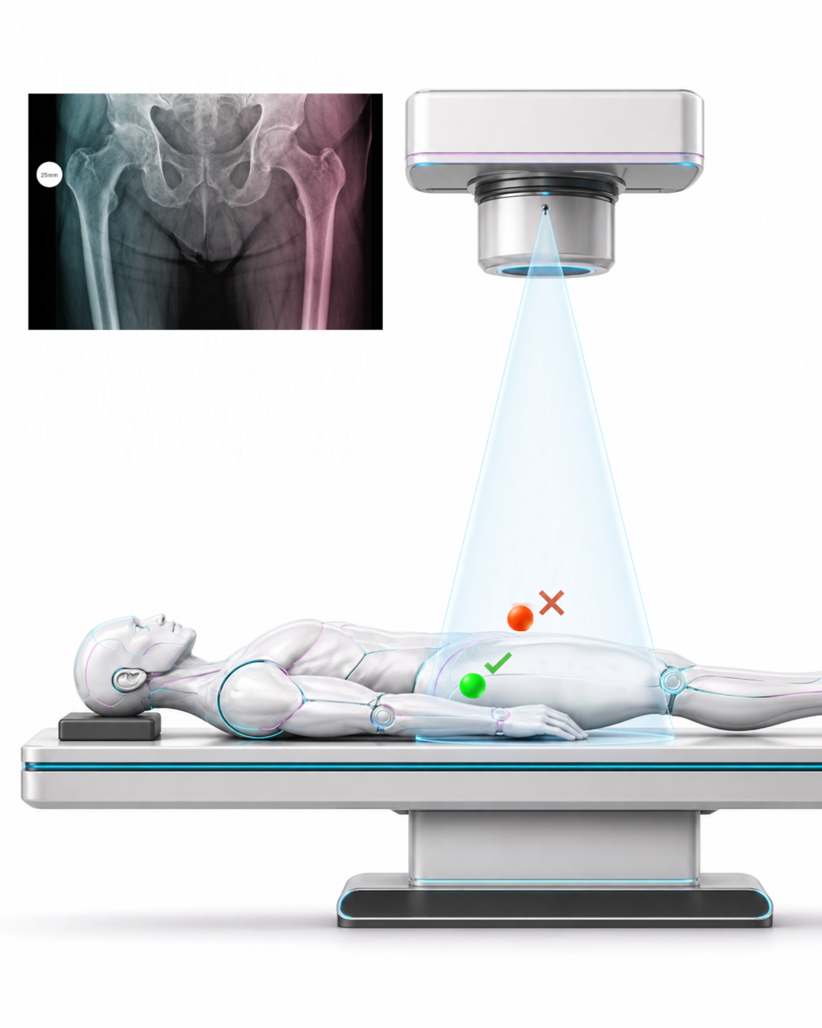
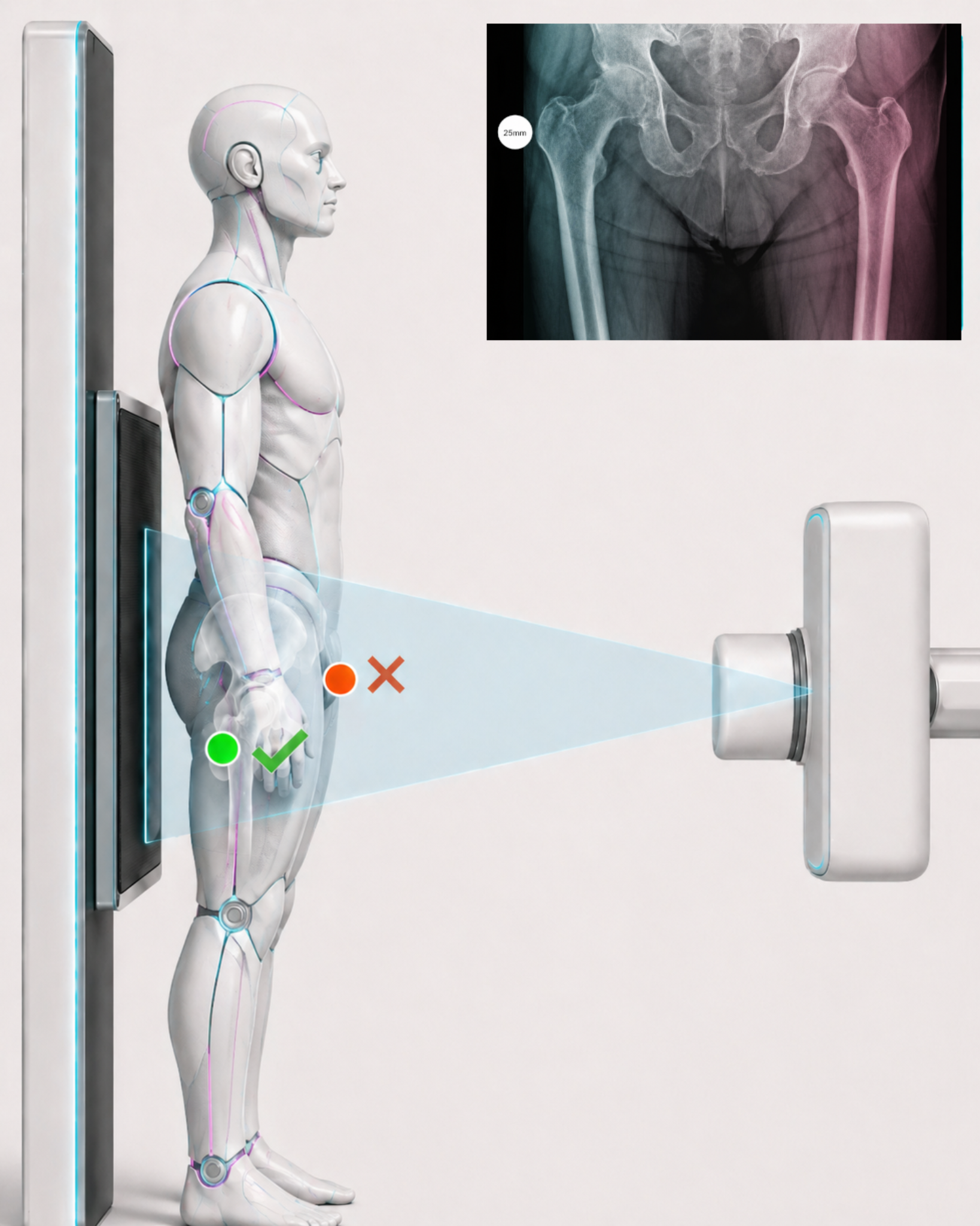
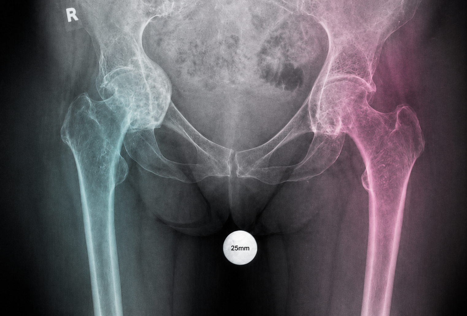
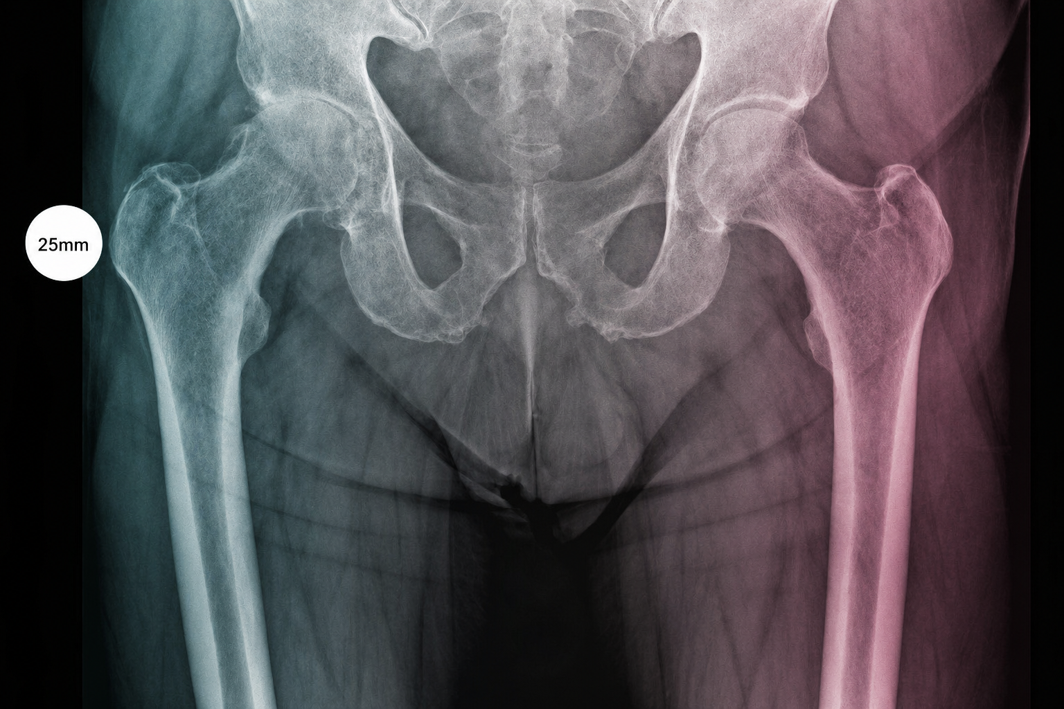
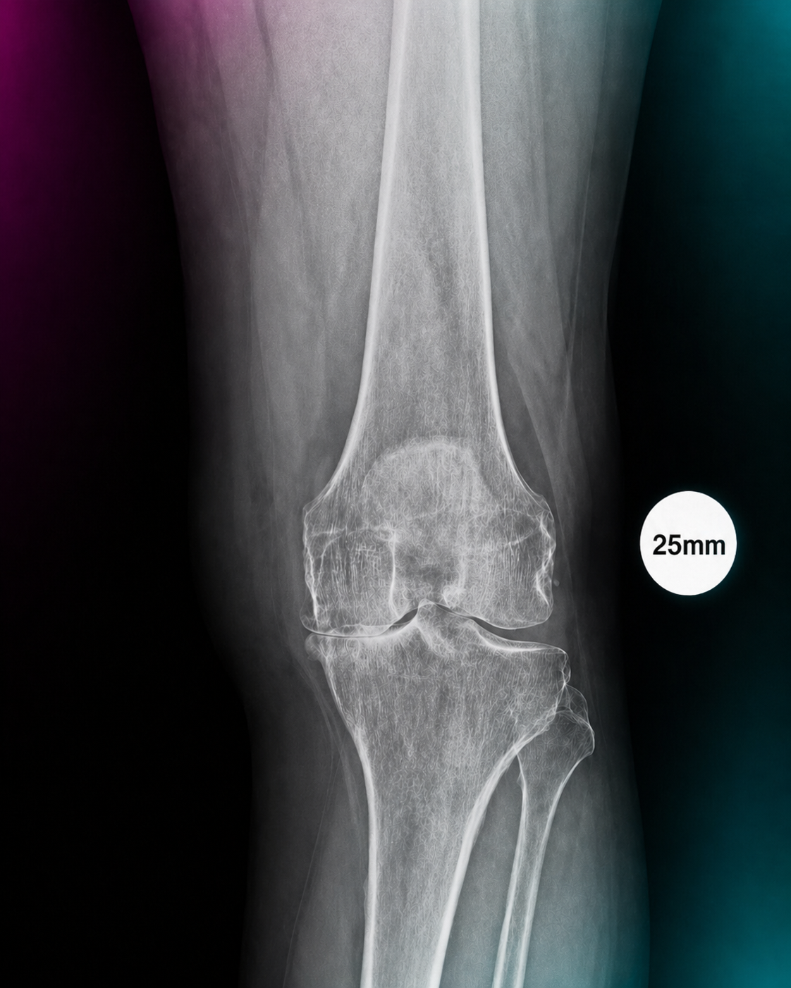
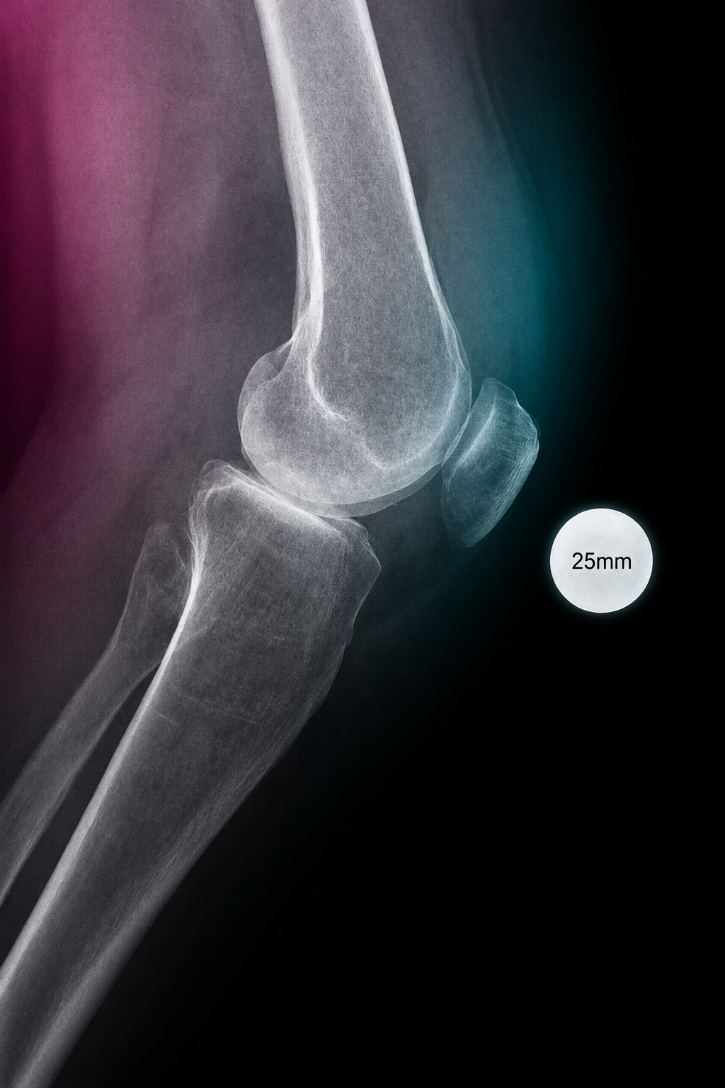
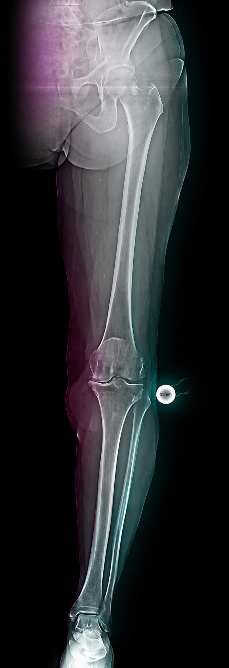
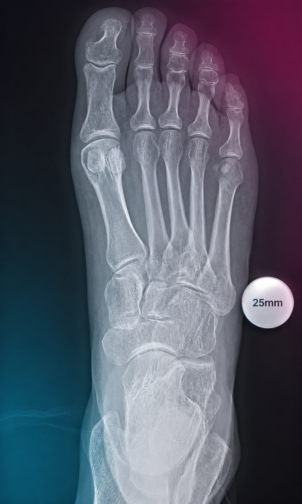
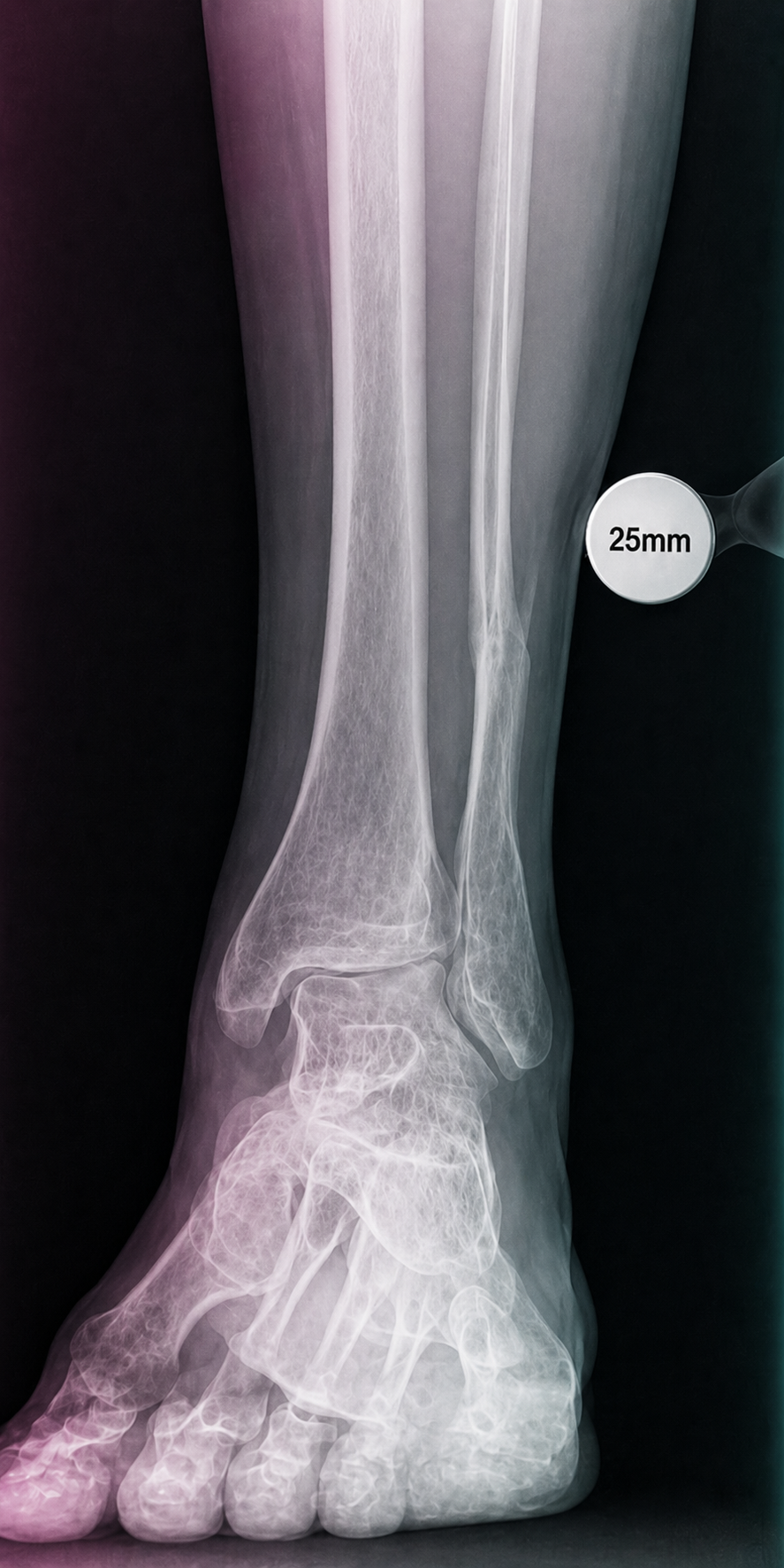
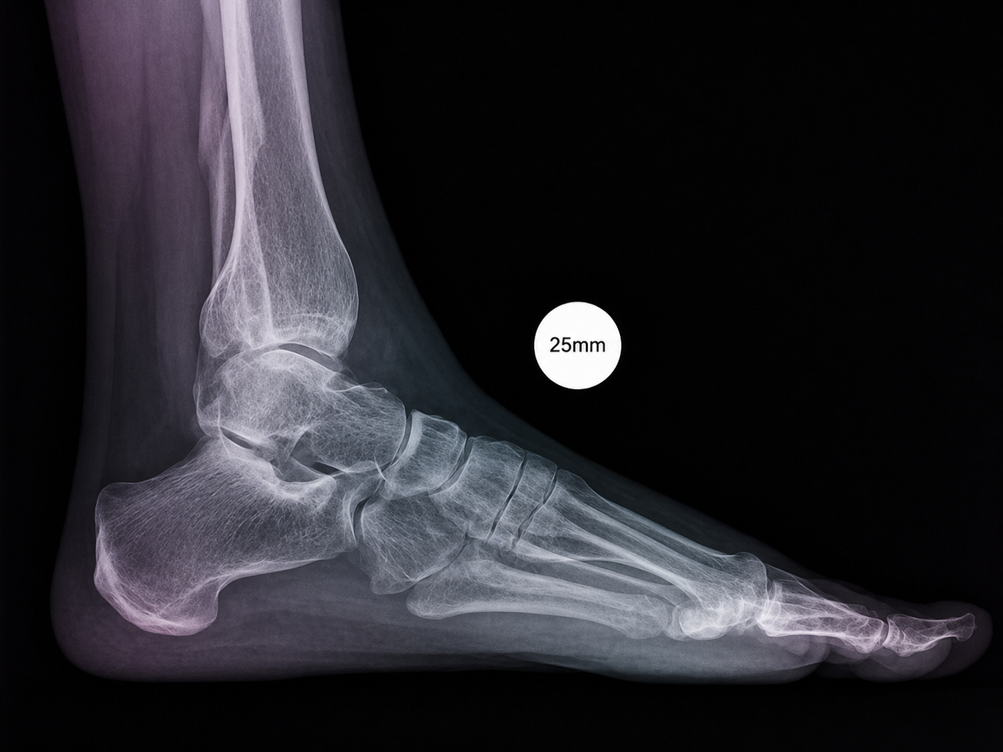
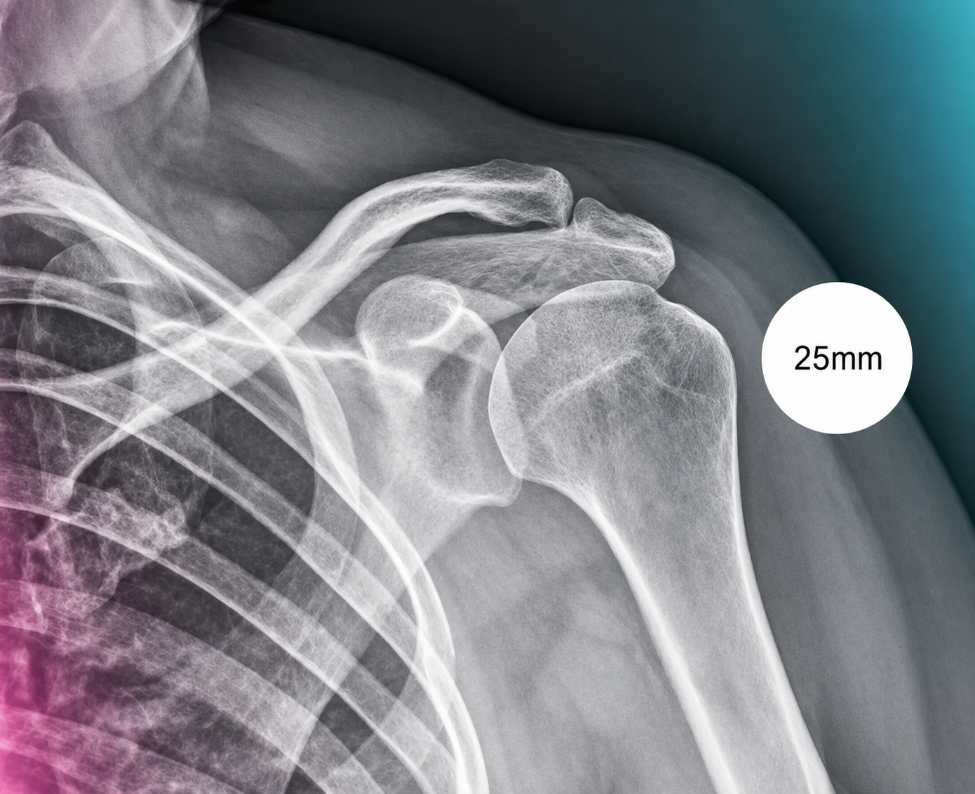
A compact guide for radiology teams on correct calibration sphere placement in orthopedic X-ray imaging. The marker must be positioned in the anatomical plane of the target joint so that digital scaling, measurements and preoperative templating remain clinically reliable.

Supine marker positioning
Standing marker positioning

Core positioning rules

  • Place the sphere at the level of the target joint or target segment.
  • Keep the marker fully visible and outside relevant bony contours.
  • Avoid abdominal, cranial or ventral marker positions that do not represent the joint plane.
  • Use standing acquisition for knee and long-leg / osteotomy workflows whenever clinically appropriate.
  • Document the marker diameter and ensure that the marker is not cropped.

Hip

AP pelvis and hip imaging require the sphere to reproduce the hip joint plane as closely as possible.

AP pelvis · medial reference
AP pelvis

AP pelvis · medial reference

Place the sphere on the level of the greater trochanter and as close as possible to the hip joint. In larger soft-tissue envelopes, a medial position in the beam path near the symphysis can be used if it better represents the hip joint plane.

AP pelvis · lateral marker position
AP pelvis

AP pelvis · lateral marker position

For AP pelvis acquisition, a lateral marker position at greater-trochanter level is suitable when the marker remains in the hip plane and fully visible. The decisive factor is depth-plane equivalence to the joint.

Knee

Knee calibration depends on marker placement at the real joint line and on correct acquisition geometry.

AP knee
AP knee

AP knee

For AP knee or partial-leg imaging, place the sphere directly at knee joint-space level. Weight-bearing acquisition is preferred whenever clinically appropriate.

Lateral knee
Lateral knee

Lateral knee

For lateral knee imaging, place the sphere in the popliteal fossa or at patellar level. Both options are valid when they reproduce the knee plane without depth mismatch.

Knee osteotomy

Long-leg imaging for HTO and DFO must combine loaded axis depiction with calibration at knee level.

Standing long-leg AP
Long-leg AP

Standing long-leg AP

Acquire the full lower limb in standing position. Position the sphere centrally at knee joint level so that hip, knee and ankle are calibrated against the loaded mechanical axis.

Foot & ankle

Forefoot and ankle imaging require the marker to match the anatomical level of the measurement target.

Hallux / forefoot AP
Forefoot AP

Hallux / forefoot AP

For hallux valgus assessment, place the sphere at the level of the phalanges / forefoot. If implant sizing is relevant, align the marker with the metatarsal level.

Ankle AP
Ankle AP

Ankle AP

For AP ankle imaging, position the sphere at talus level. If a malleolar landmark is the target, the medial or lateral malleolus may define the reference level.

Ankle lateral
Ankle lateral

Ankle lateral

For lateral ankle imaging, place the sphere at the level of the talus and midfoot axis, corresponding to the talus / second cuneiform region.

Upper extremities

Shoulder calibration must reproduce the glenohumeral plane without ventral or dorsal depth error.

Shoulder AP
Shoulder AP

Shoulder AP

Place the sphere at the level of the greater tubercle and in the beam path of the glenohumeral joint. This keeps the shoulder joint plane correctly represented.